 Serial Interface Add-On Circuit
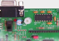
The Dragon Rider printed circuit board includes an area for a serial (COM port) interface, with level converters and a board-mounted female DE9 connector. Using this, the target microcontroller can be linked to a PC, terminal, modem or to other systems for control, monitoring and logging. A no-compromise design allows data rates up to the highest supported by the target and the cable or data transmission system.
Typical Parts Required
The table below lists the parts that are provided in the ECROS Technology add-on parts kit for the serial interface. Most of the parts are the sort of thing you may have in your spares drawer. The comments column should help you find substitutes; refer also to the Technical Information section, below.
| Qty. | Description | Ref. Des. | Comments |
|---|---|---|---|
| 4 | 0.1 µF capacitors | C13 to C16 | Charge-pump capacitors |
| 1 | 0.33 µF or 0.47 µF capacitor | C17 | Supply de-coupling |
| 1 | PCB-mount female DE9 | J33 | Footprint is for Kobiconn 152-3409 |
| 1 | MAX232-type level converter | U8 | Many sources available |
Technical Information
Click here to open a window with the schematic of this add-on circuit.
)
The serial interface circuit is independent of all other circuitry on the Dragon Rider, having only the ground connection in common, until you connect it up. Connections are made directly with wire links.
Power to the level converter IC (U8) is suppled by pin 2 (the middle pin) of J34. Normally, you will link this to target system power at pin 3. Exceptionally, you may want to power the converter from the external power supply add-on circuit, perhaps to avoid any possibility of noise being injected from the charge-pumps in the level converter. You can do this by linking pins 1 and 2 of J34. Although no header and shunt are supplied in the kit, you can install a 3-pin header as J34 and keep your options open.
Transmit Data (TXD) and Receive Data (RXD) connections to the level converter are available at labeled pads near the bottom left corner of the LCD footprint. TXD passes through a transmit channel of the converter and appears at pin 2 of the DE9, which is RXD of the connected COM port device. TXD of the connected device arrives at pin 3 of the DE9, passes through a receive channel of the converter and appears at the RXD pad. Thus, a straight-through cable should be used between the Dragon Rider and the male COM port connector of a PC. A cross-over or "null modem" cable will not work.
To connect TXD and RXD of the serial interface circuit to Port D bits 1 and 0, respectively, of the target microcontroller, simply solder wire links between the pads above and below the TXD and RXD labels on the Dragon Rider silk-screen. This turns out to be the connection needed to use the built-in UART of many of the compatible AVR devices. To use the interface with a device that does not have a UART at these port bits, or to use a software UART, you will need to figure out your own way to wire up TXD and RXD.
Hardware flow control or "hand-shaking" signals are also available at pads labeled HSO (hand-shake out) and HSI (hand-shake in). HSO passes through a transmit channel of the converter and appears at pin 8 of the DE9, which is CTS (Clear To Send) of the connected COM port device. RTS (Request To Send) of the connected device arrives at pin 7 of the DE9, passes through a receive channel of the converter and appears at the HSI pad. If you want to implement hardware flow control, wire these to general purpose port bits of your choice and drive them appropriately in software. If you read RTS as inactive at HSI, the connected device does not want to receive data from you. Similarly, if your software is not ready to receive data from the device, make CTS inactive at HSO. Note that you cannot expect flow control to take effect immediately, so be ready to receive a few more data bytes after you drop HSO. For this to work, you will need to enable hardware flow control at the connected device. If the device implements hardware flow control but you do not wire up HSO and HSI as above, you can link them together and data will flow (but without control). If the device does not implement hardware flow control or you disable it, then it is safe to leave HSO and HSI unconnected. If all this is confusing to you, just link HSO and HSI together but if you're using a high data rate be on the lookout for missed data that is sent by one side when the other side is not ready to receive it. In your microcontroller, you can watch out for this using the Data OverRun flag of the UART.
Pins 4 (DTR) and 6 (DSR) of the DE9 are wired together on the Dragon Rider PCB. So, if the PC or terminal is looking at Data Set Ready, it will go active as soon as the PC raises its own Data Terminal Ready line.
Hints and Tips
For serial communication to work, your firmware must appropriately set up the clock generation sub-system of the microcontroller's UART. For detailed information on this, refer to the device data sheet. For example, if you are using a ATmega48/88/168 family microcontroller, read sections 20.3 and 20.11 of Atmel document 2545T. Tables 20.9 to 20.12 in this document give settings for the UBRR0H and UBRR0L registers and the U2X0 bit of the UCSR0A register for a variety of system clock frequencies and desired communication bit rates (the term "baud rate" is not correct). It is not a good idea to use a combination that has an error of more than 0.5%. At or above about 2% the system will not work at all. (The error is the difference between the actual bit rate generated by dividing down the system clock and the nominal communication bit rate.) Note that the crystal supplied in the Basic Parts Kit will give a 0.0% error (ideal operation) up to 230.4 kbit/s.
The internal oscillators of microcontrollers are generally not sufficiently accurate for reliable serial communication. For example, the factory calibration accuracy of the ATmega48/88/168 family is ±10%. User calibration can improve this, but to do that you need an accurate timebase of some kind so you might as well use a crystal in the first place. Don't forget that system clock prescaler and CKDIV8 fuse affect the bit rate; see the device data sheet for details.