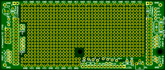
STK500 Expansion Board - LCD Version
The LCD Version of the STK500 Expansion Board is very similar to the original version, with these differences:
- There is a footprint for a 2 line by 16 character LCD and support circuits
- As a result of the above, the prototyping area is slightly smaller
- Connections to the upper 4 bits of Port D are in a different place
Other features, such as the JTAG interface, supply decoupling, etc., are unchanged and the same Parts Kit can be used to complete the expansion board. A separate kit is also available that contains the LCD and all support components. This is identical to the LCD Add-on Parts Kit of the Dragon Rider 500.
LCD Module
The footprint provided matches the Lumex LCM-S01602DTR/M 2 line by 16 character LCD Module. This is very compact and easy-to-read even though it has no backlight. It uses the very common HD44780-type controller, so it is easy to find software to drive it.
The module controller is pre-connected on the Expansion Board to the upper six bits of Port D. The data bus goes to bits 4 to 7, which is suitable for operation in the port-saving 4-bit mode. The select and enable control lines go to bits 3 and 2. You can connect the Read/Write line either to another port bit of your choosing or to a pull-down resistor for operation in write-only mode. Should you want to connect the LCD to a different port, all these connections can be broken with a sharp blade and a little care.
Note that Port D bits 0 and 1 are not pre-connected to the LCD because they often have the alternate function of the transmit and receive lines of the microcontroller's UART.
Supply Voltage and Contrast Adjustment
Because the LCD Module requires a 5 volt supply, you must set the STK500 supply voltage to something very close to this value. A resistor and trimmer potentiometer allow the LCD bias voltage to be adjusted to control the display "contrast" (which is really darkness). These are included in the Parts Kit.
Mechanical Support
The LCD module requires two pillars to support it securely. The Parts Kit contains sturdy nylon pillars, with nuts and washers to get exactly the right height for the connectors (both parts of which are also included). The module is held down to the pillars by nylon machine screws.
Assembly
Recommended component values are shown on the PCB silkscreen, so assembly is just a matter of finding and installing the parts or using the parts from the ECROS Technology kit. A 14-pin, 0.1 inch spacing header and socket pair are used for the LCD module. The header can go on the PCB and the socket on the module, but it doesn't really matter which way around these are. If you are going to use the LCD in write-only mode, add a wire jumper between the "PLDN" pad and the "R/W" pad so that the 2 kohm resistor (R3) will pull down the R/W line. If you want to be able to read the LCD controller registers as well as write, run a wire from the "R/W" pad to whichever port bit you want to control the read/write line. In this case, there is no need to install R3. The 5 kohm trimmer (R1) and 10 kohm resistor (R2) allow the LCD bias voltage to be adjusted for optimum readability.
(Click to go back to the introduction, or use the menu on the left hand side.)
