|
How it Works
|
ISO15693 /
Communication, Reader to TagThis page describes how the tag reader (VCD) uses the 13.56 MHz radio frequency operating field to send information to tags (VICCs). The ISO/IEC standard refers to this as the Communications Signal Interface VCD to VICC. By "information" here we mean a binary data packet that has a beginning and an end. What a data packet will contain and what action tags must take on receiving it will be dealt with elsewhere. We will be concerned with the representation of binary digits (zeros and ones) and how the beginning and the end of a packet are established. The problem of transmitting data over a radio frequency interface can be divided in two. First, we need to make changes to the state of the RF signal that are detectable at the receiver. Second, we need to invent sequences of signal states that will represent the elements of our data. For digital data, the binary digits zero and one (or groups of them) clearly need representations. However, if we want to send data in "packets", to transport discrete request and response messages, we'll also need representations for the beginning of a packet and the end of a packet. The ISO/IEC 15693 standard refers to packets as "frames". They begin and end with "start of frame" (SOF) and "end of frame" (EOF) sequences. Amplitude ModulationAn ISO 15693 RFID tag reader communicates with tags by changing the strength of the 13.56 MHz RF "operating field" that it generates. In general, this is called "amplitude modulation", as in AM broadcasting. For binary information, the field strength takes on one of a well-defined set of values rather than varying in a continuous manner. This can be called "Amplitude Shift Keying" (ASK), so watch out for this term when it appears in the standard (if you should have this to study). The degree of change is called the modulation index. ISO 15693 specifies two options, the reader making the choice and tags being obliged to operate with either. If the index is 100%, then the strength of the operating field changes between its nominal level and nothing at all (or, at least, a negligible level). If the index is what the standard terms "10%", then the field strength changes between its nominal level and a lower level, which turns out to be 70 to 90% of its nominal level (so the index is actually anything in the range 10% to 30%). The standard includes diagrams and tables to pin down the exact modulation characteristics, including tolerances, fall-time, rise-time and overshoot and makes rather obvious statements about the tag being able to receive all combinations of what the reader is required to transmit. To summarize, the reader can generate an RF operating field that changes between two states, normal strength and reduced strength. Tags are able to detect these state changes. Next we need to describe how sequences of these states are used to encode data. We'll need to bear in mind that reducing the field strength may interfere with the tags ability to harvest operating power. Pulse Position ModulationReductions in field strength are restricted to have a well-defined duration, after which the strength must return to normal. In the ISO standard, this momentary reduction is called a "pause" (although this should not be taken to suggest that anything stops and then starts up again). The duration of a pause is nominally 9.44 µs (128 cycles of the 13.56 MHz operating frequency), but, as already mentioned, the standard allows some deviation. Pauses are restricted to occur in either the first or the second half of an 18.88 µs "time period" (this being 256 cycles of the operating frequency). The attentive reader will immediately ask how a tag can possibly know the boundaries of these time periods, i.e. when each begins and ends, since until the reader starts sending data it is just belting out a 13.56 MHz sine wave. To answer this question, we will describe the SOF sequence before we describe the zeros and ones that make up the actual data. 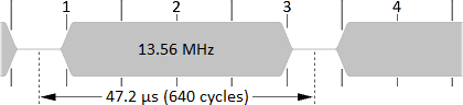 Start of FrameAn SOF consists of four time periods (and therefore lasts 75.52 µs, which is 1,024 cycles). In the first time period, a pause occurs in the first half. In the third or fourth time period, a pause occurs in the second half. This is a distinctive pattern and cannot occur anywhere except at the start of a frame. In fact, having a pause in the first half of a time period is termed a "code violation" in the standard. There, the representation of data is described first and it is simply stated that pauses occur only in the second half of a time period. Strange as it seems to make up a rule just so that it can be usefully be broken, this trick is common in the field of data transmission. The diagram above-right represents an SOF frame with the second pause in the third time period. A modulation index of 100% is assumed; use your imagination for an index of 10%. Tags can easily measure time with reference to cycles of the 13.56 MHz operating field. When a tag is waiting to receive a frame from the reader, it can look for two pauses separated by either 47.2 µs (640 cycles) or 66.08 µs (896 cycles). When it finds this distinctive pattern, it can adjust some kind of internal counter so that it is synchronized to the reader's time periods and also the beginning of the data in the frame. Inside the frame, pauses cannot be separated in this way because they must occur in the second half of a time period and so must be separated by an integer mutliple of 18.88 µs (256 cycles). Frame DataAfter detecting an SOF sequence, a tag knows where (in time) the reader is going to begin to send frame data and also where the boundaries of the all-important "time periods" are. To transmit the data of the frame, the reader counts out some number of time periods and places a pause in just one of them. Which time period it choses for the pause encodes the data being sent. Tags follow along with the count of time periods, detect the pause and decode the data. The ISO standard uses the term "Pulse Position Modulation" to describe this because the data is encoded (modulated) in the actual position (in time) of a pulse (pause) selected from a number of possible positions. This is not a good use of the term "modulation", but oh well. Note that the term "pause" has the exact same significance as "pulse" in "pulse position modulation", but avoids the implication of an increase in signal level, since the reverse is what actually happens. ISO 15693 specifies two options for the number of time periods during which one pause will occur, 256 and 4. Tags are obliged to support both and must follow along with the reader's choice. The reader can, in principle, decide which option to use on a frame-by-frame basis, but implementations will probably be designed or configured to use always the same one. The reader communicates its choice to the tags by starting the frame with either one or the other of the SOF sequences described above (so, if you've been wondering, that's why there are two). To select "1 out of 256" coding, the second pause in the SOF sequence is in the second half of the last (fourth) time period. To select "1 out of 4" coding, the second pause in the SOF sequence is in the second half of the third time period, as shown in the diagram above. 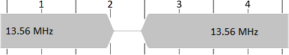 Suppose that the reader selects 1 out of 4 coding and therefore sends the SOF sequence in the diagram. For each unit of data in the frame, the reader will count out 4 time periods and place a pause in the second half of just one of them. The diagram to the right shows the pause in the second time period. The choice of time period is governed by the value of the data. With four options, the choice encodes two binary digits (4 = 22). If the two-bit data value is 00, the pause will be in the first time period, if it is 01, the pause will be in the second time period (as shown in the diagram), if it is 10, in the third time period and for 11, in the fourth. The frame data is therefore broken up into units of two bits and each unit is transmitted sequentially in a group of four time periods. Obviously, tags must not lose track of the time periods, but this is easy because their duration is 256 cycles of the operating frequency. As this is 18.88 µs, the 4 time periods will take up 75.52 µs in total. As each group of 4 time periods encodes two bits of data, the effective bit rate is 2 / 0.07552 = 26.48 kbit/s. Another way to calculate this is to observe that four time periods occupy 4 × 256 = 1,024 cycles of the 13.56 MHz operating frequency and encode two bits so the data rate is 2 × 13,560,000 / 1,024 = 26,484 bit/s. If the reader selects 1 out of 256 coding and sends the other SOF sequence, then for each unit of data in the frame, the reader will count out 256 time periods, again placing a pause in the second half of just one of them. (After a thorough discussion of 1 out of 4 coding, a diagram should not be necessary.) As before, the choice of time period is governed by the value of the data, but with 256 options, the choice encodes eight binary digits (256 = 28). If the eight-bit data value is 00000000, the pause will be in the first time period, if it is 00000001, it will be in the second time period an so on up to 11111111 for which the pause will be in the last (256th) time period. The frame data is broken up into units of eight bits and each unit is transmitted sequentially in a group of 256 time periods. This will take up 256 × 18.88 µs = 4.833 ms, so the effective bit rate is 8 / 0.004833 = 1,655 bit/s. Alternatively, 256 time periods occupy 256 × 256 = 65,536 cycles of the 13.56 MHz operating frequency and encode eight bits so the data rate is 8 × 13,560,000 / 65,536 = 1,655 bit/s. 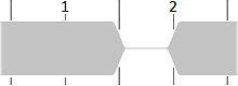 End of FrameWhen the reader has transmitted the entire contents of a frame, it sends the EOF sequence to end the frame. This is shown in the diagram at right. It consists of two 18.88 µs time periods and so has a duration of 37.76 µs. There is a single pause in the first half of the second time period. As for SOF, this is a code violation and is therefore clearly distinguishable from data, in which pauses only occur in the second half of a time period. Power Scavenging / HarvestingWe have seen that an ISO 15693 reader sends data to tags using brief and infrequent reductions in the RF operating field strength. This minimizes disruption of a tag's ability to scavenge operating power from the field. Even so, tags must be able to store energy to bridge pauses. When a zero data value comes right after an SOF sequence, three pauses occur within five time periods (but remember that the duration of a pause is half a time period). In the long term, and assuming for the moment a modulation index of 100%, 1 out of 256 coding results in a very small reduction in the average field strength — about 0.2%. 1 out of 4 coding produces a much greater reduction of 12.5%, so for 16 times the data rate we get 64 times the reduction in field strength. Implementations may prefer to use the lower "10%" modulation index with 1 out of 4 coding. SummaryTo send data to tags, an ISO 15693 reader generates brief reductions in level, called pauses, in the 13.56 MHz radio frequency signal. This is called amplitude modulation or amplitude shift keying. Data is encoded in the position of the pauses, either a pause in one of four possible time periods to sent two bits of data or a pause in one of 256 possible time periods to sent eight bits of data. This is called Pulse Position Modulation. Data is organized in frames by Start of Frame (SOF) and End of Frame (EOF) sequences. These are distinctive because they contain pauses in the first half of a time period, which is not otherwise allowed and is called a code violation. |