|
Projects
Processes
Power Tools
Resources |
Making a Handle for the Ratcheting Screwdriver This page documents how I designed and made a handle for the WoodRiver 7-Function Ratcheting Screwdriver. Woodcraft sell a "Turning Kit" for $8.50, Item # 163336, Model JS4300A-4, that includes everything you need except the handle material. The instructions (follow the link on the product page) state that 2" x 2" x 6" turning stock is required, which you can buy separately or make up from what you have on hand. In my opinion, 1½" square stock will be fine as a comfortable handle will be 1¼" or a little less in diameter. The tools that you will need are also listed, but I have made a few changes to this in my design (see below).
 Designing the HandleReviews of the screwdriver kit sometimes complain about the lack of a ferrule. This metal band's purpose is to hold together the wood where it surrounds the mechanism so that it does not split apart when a large twisting force is applied. The woodcraft instructions have you drill a ¾" diameter hole 7/8" deep in the end of the handle. For comfortable operation of the ratchet control ring, the diameter of the wood here will be about 1 1/8", which leaves just 3/16" of material around the hole. Presumable, Woodcraft feel that with a "liberal amount" of epoxy this will hold together, but I am not confident of this. For appearance, comfort and balance, I want to begin necking down the handle not too far behind the ratchet control ring and this will make things worse. So, I'm changing slightly the way that the mechanism fits into the handle to increase the thickness of the wood surrounding it. This change also drastically reduces the amount of epoxy needed and lowers the chance that it will end up where it shouldn't be (for example, in the control ring).
Prepare the Turning Blank
 Making the Hole for the Screwdriver Mechanism
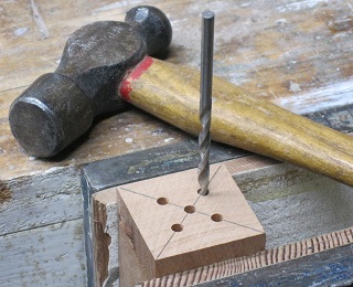
Of course, you only really need the guide if you're making several handles, otherwise you could just measure for the holes directly on each end of the blank. The middle hole is, obviously, in the exact center of the blank. The four outer holes are at 90° intervals around the center and at a radius of 5/16". These will receive the "fins" on the screwdriver mechanism.
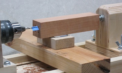
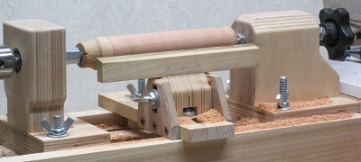
The photograph at right shows how I use the footstock in the marks on the bottom of the handle to get these holes parallel to the axis on which the handle will be turned. To advance the drill, I just slide the footstock along the bed. I prevent the workpiece from rotating by simply holding it in my hand.
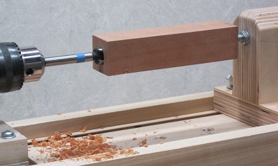
I have a fairly cheap set of Forstner bits which require quite a lot of force to push into the wood, so I lock down the footstock and advance the center spike to push the workpiece onto the bit. If you have a better quality bit, you may be able to just slide the footstock along the bed.
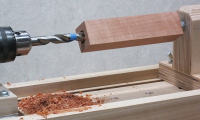
Although my brad-point drill bits aren't of any better quality than my Forstner bits, they aren't as reluctant to advance, so I can just slide the footstock forward.
Loading the Blank into the Lathe
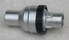
Having drilled out the holes for the screwdriver mechanism, the head end of the blank cannot be engaged by my spur drive, which is the only device that I have to locate and spin the workpiece. So, I made a custom drive "widget" that fits into the place where the mechanism will go and presents a face suitable for the spur drive. The advantage of this over drilling the holes for the mechanism after turning the handle is that the handle will end up being turned on the axis of the mechanism, which is hard to guarantee if the holes are drilled later.
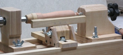
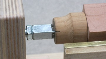 The lathe headstock is shown in closeup in a photograph on the right. The drive widget can be clearly seen with the spur drive engaged at left and insertion into the handle blank at right.
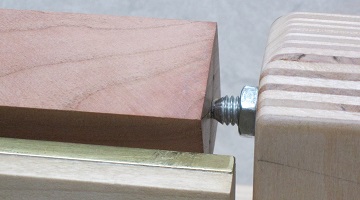 The lathe footstock (tailstock) is shown in closeup in a photograph on the right. In an earlier step, I drilled a shallow 1/8" diameter hole in the middle of the workpiece. The center spike engages in this hole to hold the tail end steady and allow the workpiece to rotate about the axis. Before running the spike into the hole, I fill it with a dab of Minwax paste finishing wax to act as a lubricant. I advance the spike until it exerts firm pressure but don't tighten it too far. I set the jam nut to prevent the spike from loosening due to vibration. From time to time, I check that the tail is still firmly held and that heat is not being generated by excess friction.
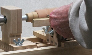 Turning the Handle
 Finishing the Handle and Mounting the Mechanism
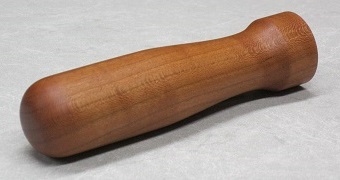
NotesThe first handle I made was curly maple. It weighed 33 grams and the screwdriver felt badly balanced when the mechanism was fitted (too light at the handle end) so I've not epoxied it in. The second handle I made was cherry. It weighed 45 grams and had a better balance, so I have epoxied this one in. The third handle I made was from glued-up canarywood with padauk and walnut accents, supposedly to hide the glue line. It weighed 46 grams. I found it more difficult than the earlier two, perhaps due to the wood's workability but perhaps just due to incompetence. I repeatedly got an unintentional spiral cut from the very bottom up the curve to the sides.
|