|
Projects
Processes
Power Tools
Resources |
Wolverine Vari-Grind Discussion(Go back to the Sharpening Woodworking Tools page.) This page was created to support a discussion of the Oneway Wolverine Vari-Grind sharpening jig and the YouTube video Ted's Turnings - Vari-Grind Experiments. I became interested in this topic while searching for a method of sharpening my skewchigouge. I tried to get a collaboration going with Ted Ross, who made the video, but that didn't work. So, this page may not make complete sense. You can skip ahead to the material I prepared for discussion with Ted, read my step-by-step breakdown of the video or continue below to read what I figured out about the Vari-Grind Jig.
 Conclusions Only — See Below for Analysis (Last Updated March 17, 2021)Some pictures in this section are stills taken from Ted Ross's video according to the fair use doctrine of the United States Copyright Act of 1976.
If you're not convinced of the uselessness of playing with the protrusion, look at the diagram and imagine increasing the distance that the tool sticks out of the jig. The tool / jig assembly will be tilted back away from the grinding wheel and the nose will ride higher. The handle of the tool will be lower, so the tool lift has been reduced. Another way to see this is to note that the intersection of the tool axis and the swing axis has been moved forward. The nose bevel angle has been decreased and the V-Arm distance must be increased to bring it back. The exact same effect can be had on the relevant geometry by moving the VariGrind leg towards the lower notch numbers. The tool handle will come down, decreasing the nose bevel angle and again the V-Arm will have to be moved further out to drop the point of contact on the wheel and restore the nose bevel. As both large and small protrusions are likely to get you into either stability or clearance problems and leg adjustment does exactly the same thing, it makes sense to just fix the protrusion at some standard value and use only the leg for tool lift adjustment.


What the Vari-Grind Jig Does For You (Last Updated March 9, 2021)The Vari-Grind Jig is intended to be used in conjunction with other parts of the Wolverine system to sharpen certain lathe tools, such as bowl and spindle gouges, on a grinding wheel. A major feature of the Wolverine system is the ability to position a "pocket" at some fixed position below and ahead of the wheel. Using the basic "V-Arm", the pocket will be in the plane of the wheel, i.e. directly in between you and the wheel. By placing the bottom of the lathe tool handle in the pocket, the axis of the tool can be held steady, which eases sharpening of, for example, a roughing gouge or a parting tool. With another accessory, the pocket can be moved to either side, which supports the sharpening of skew chisels. A limitation of this arrangement is that the axis of the tool is at a fixed angle to the abrasive surface of the wheel. There are many desirable tool grinds that cannot be achieved with this setup, so you're back to free-handing it. The Vari-Grind Jig addresses this limitation. A good general description of the system can be found at TurnAWoodBowl.
Defining a "Swing Axis"A tool with its handle in the pocket of the V-Arm and laying against the surface of the wheel will make a more-or-less fixed angle to the abrasive surface. (I write "more-or-less" because while the pocket holds steady the lower end of the tool's axis, the other end of the axis is defined by a combination of the point of contact with the wheel and the form of the cutting edge at that point. For a chisel shape, this is of no consequence). To grind a skew chisel or parting tool, the tool is just placed in the jig, first with one side against the wheel and then the other, and rubbed against the abrasive surface until the desired amount of material is removed. To sharpen a roughing gouge, the tool is placed in the jig in the same way and then rotated about its axis, alternately one way and then the other, repeatedly, so that abrasion takes place evenly around the cutting edge. (To initially establish the shape on an un-ground blank or to correct an undesired shape, grinding may not be even around the edge and you will have to control how much material is removed yourself; the jig does not help with this.) Because the jig holds the tool axis at a fixed angle to the abrasive surface, the resulting edge will have, inevitably and at all points, that same fixed angle to the tool axis. This is the desired situation when grinding a roughing gouge (at least, that's my impression). But it will not always be what you will want.
 The single purpose of the Vari-Grind Jig is to separate the tool axis from the axis around which the tool is rotated during grinding. The tool is mounted to the Vari-Grind Jig and the resulting "tool/jig assembly" is placed in the arrangement described above. The hinged "leg" (or "arm" †) of the Vari-Grind is placed in the pocket, instead of the tool handle, but the business end of the tool rests against the wheel as before. The entire tool/jig assembly is free to rotate about an axis between the tip of the leg and some point very near where the tool meets the wheel. During grinding, you rotate the assembly around this axis instead of just rotating the tool about its own axis. You can see Ted Ross doing this at at 12:25 in his video. The tool handle swings around the jig — Ted has to move his body out of the way. For that reason, I'm going to call this the "swing axis". I'm also going to use the term "neutral position" to signify the position of the tool/jig assembly when it is in the plane of the grinding wheel (or, less precisely, when it is neither swung to the left nor the right). † Ted Ross calls the hinged part of the Vari-Grind the "arm", but elsewhere it is called the "leg". I will call it the leg to avoid confusion with the V-Arm of the Wolverine system.
This is all illustrated in Figure 1, at right (which was created in SketchUp and modified in MS Paint). I've modeled the Vari-Grind as best I can from pictures on the Web since I don't actually own one. The tool is, to the best of my knowledge, a representative spindle gouge blank. I don't own any gouges either. (You can see why I wanted to collaborate with Ted Ross.) The tool axis is shown as a green line running along the bottom of the flute. You have to imagine that the tool is transparent for you to be able to see it. The swing axis, which I'm trying to define here, is shown as a blue line. Again, as it passes inside the leg of the Vari-Grind, I've made that transparent so that you can see the axis. I've also drawn a line in red which is a tangent to the surface of the grinding wheel at the point where the tip of the tool contacts it. The tool/jig assembly is in the neutral position.
Setting Up the Nose BevelBefore getting into the more interesting aspects of setting up the Vari-Grind Jig, let's quickly get a minor aspect out of the way. Without the Vari-Grind, the angle that the abrasive surface makes to the tool axis is established by how far the V-Arm pocket is extended in front of the wheel (in combination with the length of the tool). For a tool with an upper face that is parallel to the axis, such as a gouge, this will become the bevel angle of the cutting edge. For a tool that is ground on both sides, such as a skew chisel, it will be half the angle of the cutting edge. In both cases, the angle can be established with a commercial or home-made gauge or, if the edge is already correctly established, by fitting the existing tool against the wheel. Putting the tool in the Vari-Grind doesn't significantly change this procedure. Certainly, as Ted Ross shows, fitting an existing bevel angle is exactly the same. With some elementary trigonometry or just by careful drawing you could make a gauge. The Raptor Set Up Tools are designed to set bevel angles of 35°, 40°, 45°, 50° or 60° when using the Vari-Grind as long as you set the tool protrusion to two inches and the leg at 23° to the tool axis (which will set the swing axis at about 21.6° to the tool axis, depending on the shape of the tool).
For a gouge, the bevel angle is still the angle that the abrasive surface makes to the tool axis. This should be clear in Figure 1. What should also be apparent from that figure is that this angle is now made up of two parts. The swing axis is at an angle to the plane of the abrasive surface. The tool axis is held by the Vari-Grind at an angle to the swing axis. Adding these two angles together gives the angle of the abrasive surface to the tool axis and, therefore, the bevel angle. Note that the above applies only when the tool/jig assembly is in the neutral position (figuring out what happens in other positions is our goal). So, when we set things up we must do so in this position. We are then establishing the bevel angle at that precise grinding position, in other words, right at the "nose" of the tool.
Setting Up the Swing AxisHaving dismissed setting up the nose bevel as an easy problem, we come to the only other aspect of the setup that can be adjusted. To be very clear about this, with or without the Vari-Grind we have to set up the nose bevel, but when we put the tool in the Vari-Grind we have one, and one only, additional thing to establish. This is the angular difference between the tool axis and the swing axis. These are the only two parameters of the entire grinding setup that will affect the shape of the ground tool edge. It does not matter how many different things you can find to adjust, it all boils down to nose bevel and swing axis. (This is my major issue with Ted Ross's video, as, in his whiteboard session from 4:22 to 4:57, he identifies "three jig settings" and appears to imply that these allow independent control of "nose bevel, flute wing sweep and flute wing shape".)
It's not at all hard to figure out how to set the angle between the tool axis and the swing axis if you just play with the tool/jig assembly for a while, either in your hands or in your mind. The hinged leg of the Vari-Grind can be set in various positions (or anywhere in a range of positions for the Vari-Grind 2). Each position has a strong influence on the angle. With the leg up close to the tool, the tool axis will be only slightly different from the swing axis. At the other end of the leg's adjustment range, it looks as if the tool axis could be around 45° away from the swing axis.
 In Figure 1, the angle between the tool axis and the swing axis is 25° †. To obtain a 40° nose bevel angle, the swing axis is 15° above the plane of the abrasive surface (because 25° + 15° = 40°). As we discussed above, that angle is obtained in the usual way by adjusting the position of the V-Arm pocket after setting the tool axis to swing axis angle and locking the position of the Vari-Grind's leg. Figure 2 shows the swing axis only 18° from the tool axis. To achieve this, the leg has been moved up, perhaps about as far as it will go. To get back to the 40° nose bevel, the angle between the swing axis and the abrasive surface has been increased to 22° (18° + 22° = 40°). This is done by moving the V-Arm pocket further out from the wheel, allowing the tool to ride lower. Figure 3 shows the swing axis increased to 40° from the tool axis. The leg is a few degrees short of its lowest position. Now the angle between the swing axis and the abrasive surface must be zero to get a 40° nose bevel. The V-Arm pocket has been brought closer in and the tool rides higher on the grinding wheel. † This may or may not be a possible setting of the Vari-Grind. I don't know this because I don't have access to a Vari-Grind Jig. I'm starting to suspect that the notches are not, in fact, detents, and that you can set any angle that you want, as with the Vari-Grind 2.
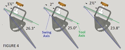 The tool protrusion will also have an influence on the tool axis relative to the swing axis. Note that the swing axis lies between the tip of the Vari-Grind leg and some slightly vague point up near the tip of the tool; it does not lie along the middle of the leg. I have not found a reason for setting the protrusion to any particular value. Both Kent Weakley and Woodturner Ky state that you should set the protrusion to two inches and be done with it. Craft Supplies USA does the same, but suggests that to grind a secondary / clearance bevel under the main bevel of a bowl gouge you can increase the protrusion to two-and-a-half inches without making any other changes to the setup. Figure 4, at right, shows the tool / jig assembly modeled in SketchUp with three values of the protrusion for the same position of the leg. In the middle, the protrusion is the "standard" two inches and the angle between the tool axis and the swing axis is 25° (this is just another view of Figure 1). At left, the protrusion has been reduced to one-and-a-half inches and the tool axis to swing axis angle has increased to 26.3°. At right, the protrusion has been increased to two-and-a-half inches and the angle has decreased to 23.8°. This is not particularly interesting; the only point of the diagram is to show that I'm not mistaken when I state why the protrusion matters. Don't get any of these figures mixed up with the bevel angle; that must be set as a second step as had already been explained.
We've not yet come to how you would decided where you want the swing axis to be relative to the tool axis. We're hoping to figure this out so as to answer the question Ted Ross poses at 0:24 in his video. But, we've not got there yet. You will, however, need to make this decision before establishing the nose bevel angle. If you move the Vari-Grind leg after you've set the bevel angle, you'll just mess that up and have to do it again.
Setting Up — SummaryFirst, put the lathe tool (which we assume is round) through the holes of the Vari-Grind and run the screw clamp down to hold it in place. Make sure it is rotated to be "flat" when the assembly is presented to the wheel in the neutral position. Its protrusion might as well be two inches unless you come up with a good reason for it to be otherwise. Second, unlock the hinged leg of the Vari-Grind, move it to the desired position and lock it back up. We don't yet know how to choose the position. Finally, using the whole assembly instead of just the tool, adjust the V-Arm pocket so that the tip of the tool makes contact with the grinding wheel at the desired nose bevel angle, making sure to hold the assembly in the neutral position. (You can only use a commercial set up gauge, such as the Raptor, if you have set the tool protrusion and leg position in the way that the manufacturer specifies.) Now you are ready to turn the grinder on, touch the tool to the wheel and swing right and left until you have removed the desired amount of material.
So, What Exactly Happens?Now we come to the really tricky part, which is figuring out what exactly is happening as you swing the tool and Vari-Grind assembly around the swing axis with the tool on the spinning grinding wheel. To sneak up on this information gradually, I propose to make two simplifying assumptions (one of which we may re-visit later) and then to consider only the most tractable positions in the swing. I will also introduce concrete examples. After that, we can strategize on how to complete the general analysis.
Simplifying AssumptionsThe first simplifying assumption is that what happens is not affected by the shape of the tool when grinding begins, nor by how much material you choose to remove at each point in the swing. You could decide to stop reading at this point, because that assumption will limit the scope of our conclusions to the maintenance of an existing satisfactory grind. It may leave us in the dark when it comes to establishing the edge shape on a tool blank or changing the shape in any significant way. Nevertheless, I don't think it will be possible to reason precisely about the grind profile unless we make this assumption. We may, however, come up with some useful guiding principles. Note that at all times during grinding, the shape of the tool edge at that moment will slightly influence the position of the top end of the swing axis because it will affect how far the tool axis rides "above" the abrasive surface. We are perhaps justified in ignoring this. So, what we're really concerned about is the lack of any reference for how much material should be on the tool at each point in the swing so that we know when to let up. (This is why I decided that the Vari-Grind did not meet my needs, forcing me to design my own jig, and in the process confusing the hell out of Ted Ross.)  The second simplifying assumption is pretty harmless and I'm hoping that nobody will take issue with my suggestion that it won't change any conclusions we make. It is that the abrasive surface is not a spinning cylinder of a certain radius and width but instead is a flat sheet that has the magic property of removing material pressed up against it. The angle of the sheet to the tool corresponds to the tangential angle of the real grinding wheel. Since we obviously intend to prevent the tool from slipping up or down on the wheel or from falling off the side, the only result of our simplification is that we're ignoring the slight "hollowness" in the grind. Neutral and Ninety-Degree PositionsIt's pretty clear what happens in the neutral position (where the tool / jig assembly is straight-up-and-down, not swung to the left or to the right). We've been careful to set things up so that the tool axis makes a specific angle, for example 40°, to the abrasive surface. If we're starting with an unground tool blank, the bottom edge, under the nose, (perhaps, therefore, the "chin") will be the first part to contact the abrasive. As grinding progresses, a face will develop and spread until it reaches the upper surface of the tool, at which point we're done grinding in this position. Figure 5 attempts to illustrate this situation. It shows a gouge blank, so the upper surface is the bottom of the flute. This surface runs parallel to the tool axis. Therefore, we've successfully defined the nose bevel angle, in this case 40°. If you're not starting with a blank, then the pre-existing face will contact the abrasive and removing a small amount of material will sharpen the edge at this point.
 Now let's swing the tool/jig assembly 90° to the right. In your mind's eye, with the help of Figure 6, go around to the left side of the grinding wheel to see what's going on. The tool and the Vari-Grind lie in a plane. This used to be straight up-and-down, forward-and-back, i.e. in the plane of the grinding wheel. But now it is swung over by 90° and is at right angles to the plane of the wheel and instead parallel to the axis of the grinder. The axis about which it has been swung is clearly in the same plane, from the tip of the tool to the bottom of the Vari-Grind leg. This axis has not moved (but read on). The angle between the tool axis and the abrasive surface is therefore now the angle between the swing axis and the plane of the abrasive surface. Referring back, recall that this is the nose bevel angle minus the angle between the swing axis and the tool axis. For example, if we have set the swing axis at 25° relative to the tool axis and then set the nose bevel angle to 40°, our plane is at 15° to the abrasive surface. Since the plane contains the tool, this is the angle at which we are grinding the tool where it comes into contact with the wheel. Unfortunately, Figure 6a shows that if we press the tool down enough that the swing axis stays in the same place (with respect to the neutral position), then we are grinding half way across the nose of the tool and will eventually end up with a sharp point and not a lathe tool at all. For what we're doing to be useful, we must allow the tool to lift up from the abrasive surface as we swing away from the neutral position. Figure 6b shows the situation when we lift the swing axis away from the grinding wheel by 1°. It's certainly more realistic, but why 1°? There is no justification for a particular value. Even in this simple case, we've lost the ability to understand what the Vari-Grind is doing for us unless we fill in details of the specific situation.
 If we disregard, for a moment, tilting the axis up as we swing the tool over, then we can draw one useful conclusion. When we reach a swing of 90°, as illustrated in Figure 6, we know more-or-less the angle that the abrasive surface will make to the tool. To make this clearer, Figure 6c is a different view of the situation with everything but the tool and the abrasive surface hidden and the viewpoint moved above the tool. The abrasive surface has a check pattern to help show its position in three dimensions. First, the abrasive surface is straight-up-and-down, with respect to the natural orientation of the tool, i.e. it does not lean over the top of the tool or angle inward underneath. This is a direct consequence of having swung the tool / jig assembly over by 90°. The natural up-and-down direction of the tool started in the up-and-down plane through the grinding wheel. Now it is flat across the wheel. Shifting our viewpoint to the tool, the plane of the abrasive surface went from side-to-side (although tilted under at the nose bevel angle) around to straight up-and-down at the side. (Tilting up the swing axis to get the desired depth of grind does not change this observation.) The angle that the abrasive surface makes to the side of the tool (which is, of course, parallel to the tool axis) is, as we observed above, the nose bevel angle minus the angle between the swing axis and the tool axis. In our example, this is 15°. Other Swing PositionsIf we can imagine shrinking ourselves down to a fraction of an inch in height and strapping ourselves into a chair fixed part way back in the tool flute, then this is what we'll see as the tool / jig assembly is swung from the neutral position to 90° to the right :

Figure 7 shows the leg-at-second-notch setup at 45° of swing (to the right). If it helps at all, I think it shows how hard it's going to be to visualize what's going on throughout the swing if we stick to this viewpoint. So, as we move on towards a better understanding, we'll use diagrams in which the viewpoint is in the tool flute. We'll also hide all the distracting elements of the model so as to focus on the relationship between the abrasive surface and the tool. It must be stressed that there is nothing "magic" about 90° of swing other than that the abrasive surface is straight-up-and-down, whatever the leg and nose bevel settings. This is not where you are obliged to end the swing unless the tool lies flat on the abrasive surface, as it will in the Figure 3 leg-at-fifth-notch setup.
An Improved Visualization
Step-by-Step Through Ted Ross's Video (Work In Progress, Last Updated March 10, 2021)0:00 to 2:12 — Introduction : Ted states the question that he intends to answer in the video (at 0:24), describes how it came about, and summarizes the video content. The question is "... if I set the arm here or here, how's it change, does it change my bevel, does it change the wing of my tool, what does it change, exactly." 2:13 to 2:43 — Wolverine jig : Ted displays and describes the jig parts and various accessories such as the Raptor set up tools. 2:44 to 4:23 — Bowl gouges : Ted displays and describes his gouges and, in particular, one with a bad grind that he intends to rework. 4:23 to 4:57 — Whiteboard Session : Ted stands in front of a whiteboard and lists, first, "three ... considerations for sharpening a ... gouge" (nose bevel, flute wing sweep and flute wing shape) and, second, "three jig settings" (protrusion, arm position and distance to wheel). This scene implies that there is some level of engineering analysis behind what is to follow. It also implies that the three settings, between them, determine independent outcomes for the three considerations. Both implications are false, refer to the analysis, above. 4:57 to 6:08 — Nose Bevel : In the usual way, Ted grinds the nose bevel of his badly ground bowl gouge to 40°. He explains that he will use this later to retain this bevel angle when he puts the tool in the Vari-Gind jig. 6:09 to 7:12 — Number Two : Ted sets up the gouge in the Vari-Grind with the leg / arm at the second notch. He resets the nose bevel, makes a test grind and examines the results. 7:13 to 8:23 — Number Five : Ted moves the Vari-Grind leg / arm to the fifth notch and repeats setting the nose bevel, making a test grind and examining the results. The grind is lower on the wing and sweeps further back from the nose. 8:24 to 8:56 — Number Two, Reprise : Back at the second notch, Ted finishes regrinding his badly ground bowl gouge. He proclaims the result "not too bad", notes the 40° nose bevel, straight wings and makes some other (unsubstantiated) quantitative observations. 8:57 to 9:44 — Swept Wing, Step 1 : Ted explains what he doesn't like about the present grind of his swept wing bowl gouge and does some free-hand preparatory work. 9:45 to 11:03 — Swept Wing, Step 2 : In the now familiar way, Ted sets up the gouge in the Vari-Grind and establishes the nose bevel. The position of the Vari-Grind leg / arm is almost certainly at the fifth notch. On finishing the grind, he notes that he could have set the leg / arm at the fourth notch but does not explain why. The nose is "a little pointier", which he proceeds to correct. 11:04 to 11:36 — Swept Wing, Step 3 : Ted grinds the nose rounder. 11:36 to 13:36 — Double Bevel : Ted grinds a second (clearance) bevel under the main bevel (and then a third). He shows that, as an alternative to moving the V-Arm, you can increase the tool protrusion. 13:39 to 15:28 — Answering the Question : Ted shows in close-up the two tools that he has ground, one with the Vari-Grind leg / arm at the second notch and one with it at the fifth notch. He admits that the bevel angles are different and the tool diameters are different. Nevertheless, I think that his observations about the differences in the wings are probably valid. This is a key part of the video. 15:29 to 16:23 — Wrap Up : Ted summarizes the video and wishes us "happy turning". The summary of the previous section, the answer to the question, is messed up by an inset in which he is not pointing to the part of the tool he is talking about, so this is best ignored.
 Intended for Ted Ross (Last Updated January 26, 2021)The figures at right, exported from SketchUp Make, illustrate my basic approach to modeling the grinding of a lathe tool. The first figure shows a tool blank (grey) and a "grinding cone" (orange). As described in comments to the video, the grinding cone results from a change of reference frame from the normal one in which the grinder is static and the tool is swung back and forth to the tool itself. The abrasive surface of the grinder now sweeps out a cone as the tool is swung. We then assume that all material is removed from the tool blank outside of the grinding cone. By using SketchUp to find the intersection of the two shapes (and a lot of manual fix-up), we can then arrive at the ground tool shape, which is shown in the second figure.
 I've created grinding cones with apex half-angles of 10, 12, 15, 20, 25, 30 and 40°. It's not a lot of trouble to create others. They are all tipped up by their half angle and their axes go through the SketchUp origin. This makes it easy to visualize the abrasive surface when the tool is in the neutral (center) swing position; it is just the horizontal plane. If you then imagine the horizontal plane swinging from side-to-side around an axis angled upwards by the cone half-angle, then you will see that it sweeps out the surface of the grinding cone. I've created four lathe tool blanks. They are shown in the third figure, below right. From left to right, they are my interpretation of a roughing gouge, a bowl gouge, a spindle gouge and a skewchigouge. Only the skewchigouge is accurate; the others are guesses based on peering at on-line images. (Remember always that I barely know what I'm doing with a lathe, have only the skewchigouge and a skew chisel made from an old metal file and I've no intention of spending hundreds of dollars on new tools. Most of the reason I'm doing all this is to make sure that my mind and body continue to function in retirement.) For scale, the blanks are lined up at intervals of one inch. The roughing gouge has a semi-circular cross-section, the outer diameter is ¾" and the inner diameter is ½". I'll listen to advice on the shape of the blanks, but now that I've got a good start with the skewchigouge most of my effort will go in that direction.
Since the neutral position of the abrasive surface is the horizontal plane, the bevel angle in the middle of the ground tool is established simply by tipping up the tool at the desired angle. In the example of the roughing gouge, I chose 40°. Since the axis of the grinding cone is tipped up by the same amount, it is parallel to the tool axis. For this example, I've made the axes of the cone and tool exactly the same. As a result, the bevel angle remains the same around the tool edge. Swinging the tool just presents a different part of the edge to the abrasive surface. As I tried to explain in my comments on the video, there is nothing about the Vari-Grind jig that controls the relative positions of the cone and tool axes. The jig certainly influences this, particularly the angle they make to each other, but the lateral position is strongly influenced by the starting grind and changes as the grind progresses. With what I have modeled in SketchUp it should be possible to explore the effect of this variable. For the skewchigouge, I have chosen to eliminate this variable by building a jig that controls the positions of both axes. |